|
Gunderson
Double Stack Construction - Part 2
"The Inside Story"
In building the Gunderson
car there are several parts to consider that are on the inside of the
car. Most of the time one would not see the interior, However, to keep
the car prototypical we need to make the inside parts as close as possible.
The containers that you have seen riding in the cars are not resting on
the bottom of the cars. Actually, the containers are hanging from the
side of the car on what I am going to call 'the feet'. The feet are made
from very heavy metal and are connected to braces and brackets welded
to the sides of the car. There are three sets of feet - one on each end
and one in the middle. The middle one, I assume, is for short containers.
The feet are connected by cross bracing and x bracing on the bottom of
the car. This keeps the car sides parallel. The cross bracing at the feet
are attached to the car with a hinge assembly. This car with long sides
probably will twist fairly easy. I would guess the hinge assembly lets
the car move with out breaking the welds.
| In this
photo you will see all the hinge and feet parts. I made the hinge
solid since I don't expect my car to rack much. I put lines on the
5/16 rod using the lather to simulate the joints. |
|
|
Here is the back bracket
for the feet. The side braces have already been welded on. The holes
are to weld through to weld the foot on to the side brace. Using a
plug weld the weld can't be seen from the front. |
| Here's the
hinge rod welded to the foot bracket. The holes are for plug welding
the foot on to the back bracket on the real car. I just left the holes
and welded on the back and bottom. Photo 3 a shows completed hinge
bracket. Slots are for welding on the cross bracing. |
|
|
Addition of the intermediate
brackets. There are no hinges at these locations but the bracket
itself will flex to some degree. It was interesting to note that
the G scale model I purchased as a guide for some construction details
and the paint scheme, had incorrect location of the bottom cross
bracing. Actually, the model had an extra set of cross braces.
|
|
|
|
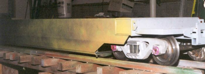
The sides were welded
to the end assembly before any of the cross bracing was installed.
The top photo shows the car on its wheels for the first time on
Dec. 25, 2001. The bottom photo shows another view.I will be taking
some outside photos for better lighting soon.
|
|
These photos show the
cross bracing clamped in to place. Everything is checked for level
and location before welding begins. As you notice, one never has
enough "C" clamps.
You can see, I have a
sea of "C" clamps!
Couldn't resist that one. Sorry.
|
|
Here are some new pictures from January 6th showing the car as Lee continues
to add details.
(Click for larger view)
Continue
to Gunderson Car Construction Part 3-->
|