|
Repowering
the SD-6060
Installing the E-tek
and Sevcon Controller
A few years back we
started installing the E-tek motor and Sevcon controllers in our locomotives.
The SD-60 Number 6060 was the last of five units to get the treatment.
There are a couple articles on this site that show the conversion of two
of the locomotives.
These photos show
the set up that we have been using for several years with out a single
problem. Mark ran his SD-60 for 9 years before his was converted.
The reasons we made the switch to the E-tek set up are as follows.
The DART controller was only rated at 60 amps. The DART controller was
real sensitive to reverse current, say switching to reverse while still
traveling forward. That would basically destroy the controller.
There were some safety things that I built into the circuit to help protect
the controller. However, it was not 100 percent effective.
One still had to make sure you stopped before trying to reverse the motors.
Reason number two is space. The Sevcon takes up about 1/3 of the space.
All the solenoids are built into the Sevcon. The Sevcon is rated at 300
amps and no problem reversing. Although I had an emergency stop built
into my electrical system, it was an all or nothing. The Sevcon can be
set to apply the brakes by percent thus stopping but not so fast as to
throw someone off or damage the equipment.
This photo shows the
two motors connected together end to end. Together they would put out
2-1/2 electrical H.P. It was enough to spin the wheels on the 1,000 pound
locomotive. Those are 36 volt motors rated at about 30 amps.
These photos show
all that time and hard work designing and building the system all gone.
Stripped down to the bone.
Here you can see that
two of the up right motor brackets had to be removed also. Lots of sawing
and grinding for that job.
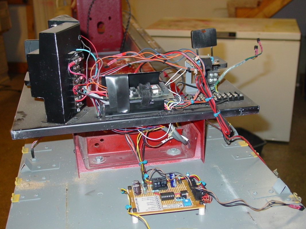
Below, I have the
new motor bracket install and now locating the placement of the new parts.
Important nothing hits the body or is impossible to get to. Note that
the controller is mounted on an aluminum plate. The plate is about 3/4"
off the channel and heat sink caulk is used between the controller and
the plate. Same with the 36 to 12 volt converter.
Next, the layout is
coming together. It is basically one big circle.
The first battery plus is connected to the contactor. From the the contactor
to the controller. Battery negative from the controller continues on to
the front two batteries and then all the way to the back battery negative
to complete the loop.
Photos 11 and 13 show
the motor pulley set up. Since we have more than tripled the H.P. I re-geared
it to run a little faster. Well… a lot faster. Steam engine guys
look out. I will be tail gating you. Well…not really, I would not
tail gate as it is unsafe.
Now we see the cab
and all the wires to run the number boards, head lights, class lights,
deck lights and ground lights.
Plus the ditch light flasher board. Oh yes, the sound card was up there
also. There were seven circuit boards. I didn't even remember what two
or three of them were for.. Bummer they were all removed.
Sixteen and seventeen
show the control console. I added the gauges and back lit them. I drew
them up on AutoCAD and printed them on my printer. They are real little
and hard to print. They do look cool at night though.
I had the engine out
and gave it a test run. It runs great and sounds great with the new Phoenix
sound card.
|