| SD-60
Construction |
|
The following photos shows some of the construction
techniques I have developed over the past 15 years. Most locomotives I
have observed have an open frame type construction. The frames and components
used in the construction of the SD60, GP-40 ,c30-7 and SD-40 are made
to resemble EMD and GE frames close as possible. The following photo sequence
will take you through some of the steps in building a locomotive. As I
filter through my photo collection, we will try to add in some of the
missing steps.
Click on thumbnail
to see a larger picture.
|
|
|
|
Motor bracket was the first part made and is being
compared to the full size drawing. |
|
|
|
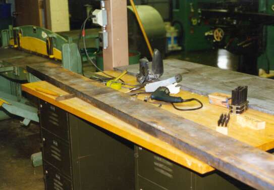
1/2" holes were drilled at several locations down
the center of the 8" channel used for the main frame. The holes will
be used to hold the 109" channel on the bed of the Bridgeport milling
machine. |
|
|
|
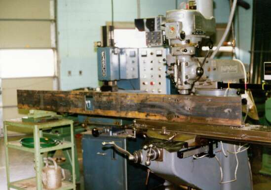
The Bridgeport is used to locate holes in the frame
and square out the hole that will be used to contain the drive belt. |
|
|
|
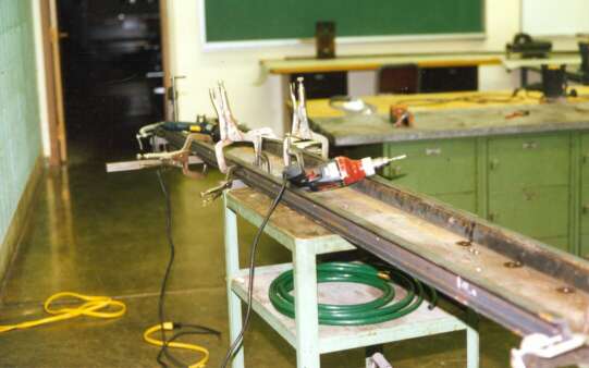
1"x2" channel is connected to the sides of
the 8"x2" channel to help make the frame more rigid and give the
locomotive frame that prototype appearance. |
|
|
|
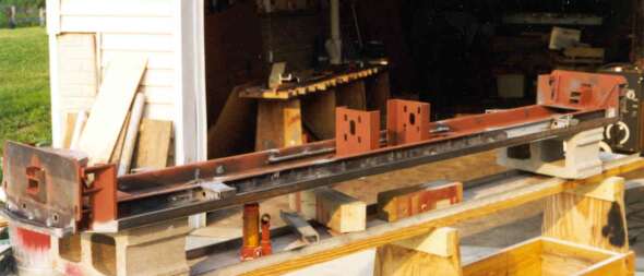
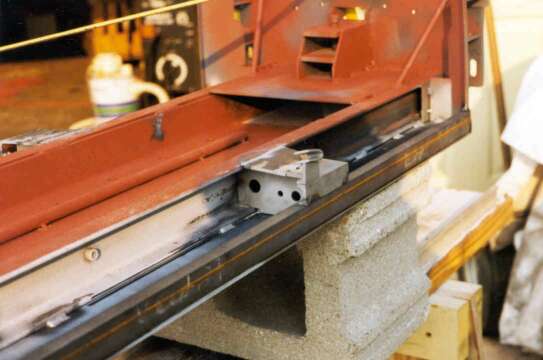
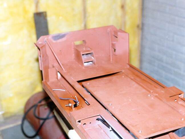
This photo shows the completed bottom section with
the bearing brackets welded in place. Note fuel tank side fitted to underframe.
|
|
|
|
This photo shows the locomotive frame. |
|
|
|
This is a closeup of the frame. |
|
|
|
Skipping to truck castings. Casting is set up on Bridgeport
and supported from under the main side of the casting. Bolster pads are
machined to equal height and are later used as contact points when casting
is inverted.
|
|
|
|
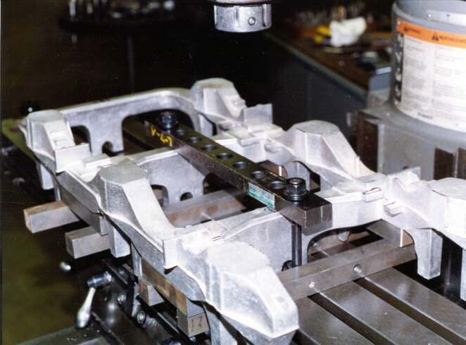
Truck casting is mounted on Bridgeport and wiggler
is used in conjunction with digital readout to note all the pedestal locations
on the rough casting before any machining is begun.
|
|
|
|
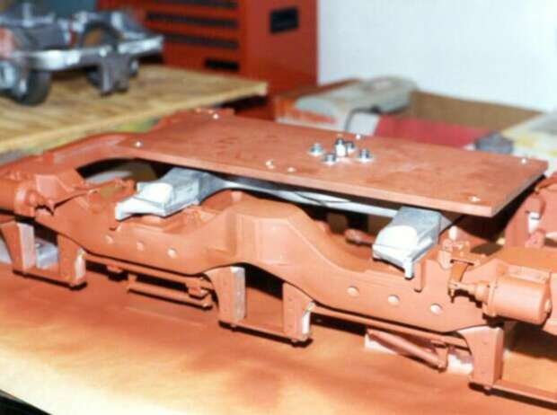
Jumping ahead several steps. ( I will look for more
construction photos) We see the span bolster fitted to the truck casting.
Note how the bolster is connected to a plate and not to the
locomotive frame. |
|
|
|
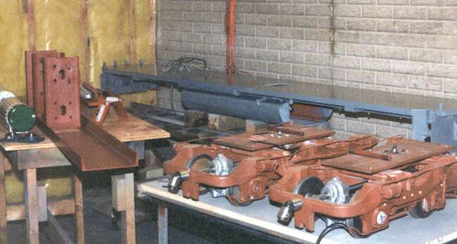
In the background we see the completed frame.To the
left we see the motor channel and to the right the completed trucks. |
|
|
|
Frame is inverted showing back of coupler pocket, step
sides and truck mounting plate. |
|
|
|
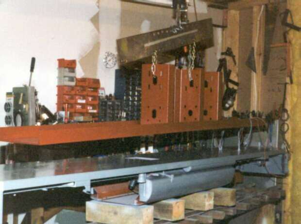
Milestone is reached at this point as the top motor
channel is lowered into place onto the bottom frame The sandwich of the
two 8" channels 2-2" channel and the 11 gauge deck material will
all serve to hold up the 850 pounds of locomotive with out getting a sway
back. . |
|
|
|
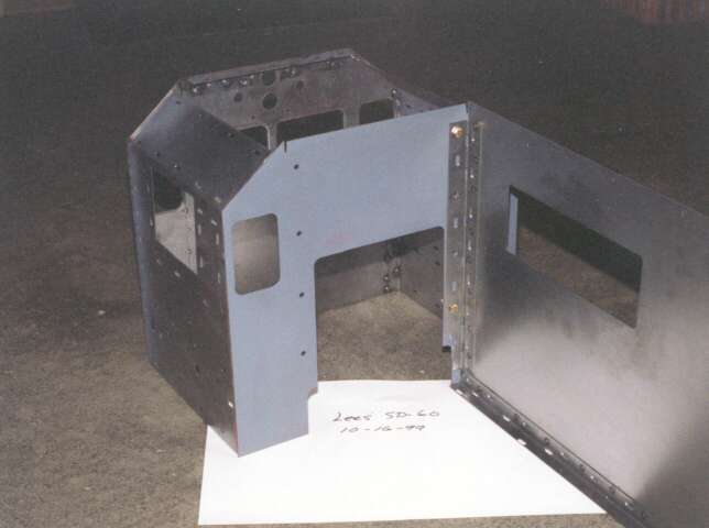
Showing back of cab and side panel for SD-60 |
|
|
|
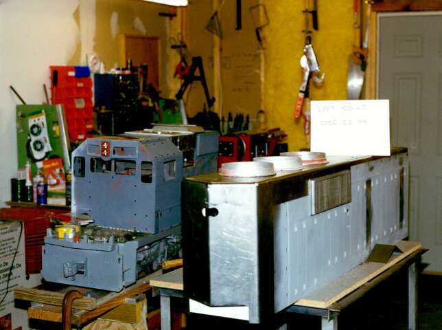
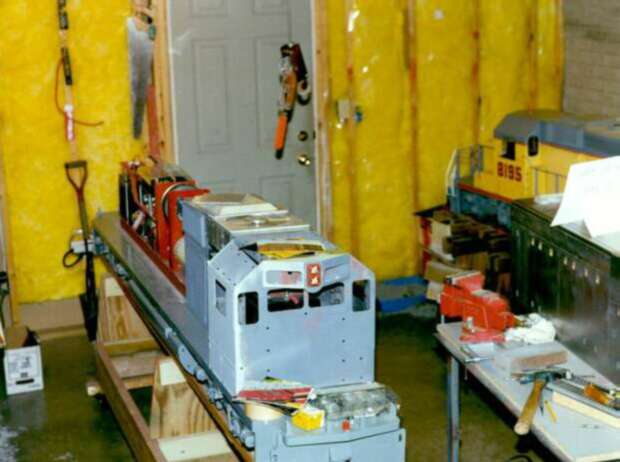
Looks like the date in the card is Dec. 22.1999. Lots
of work to be completed yet. |
|
|
|
Still some assembly required. |
|
|
|
All the major sub assemblies are now in place. |
|
|
|
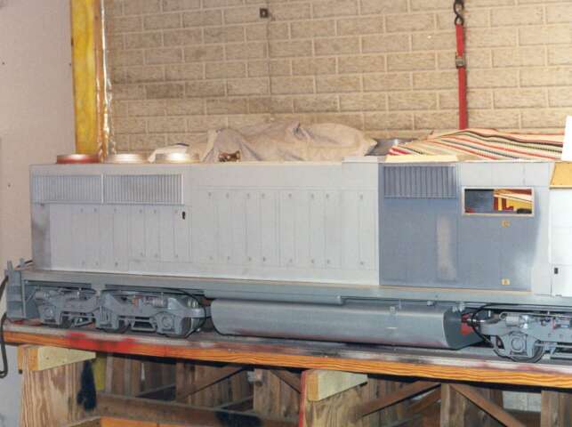
Front section complete and top painted grey. Cat walks
on top has to be repainted. Where's my gun? |
|
|
|
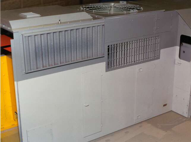
Rear section 98% complete. |
|
|
|
Rear section ready to mount on locomotive frame. Entire
locomotive is painted with spray cans. just keep it wet but not too wet.
|
|
|
|
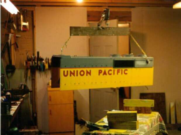
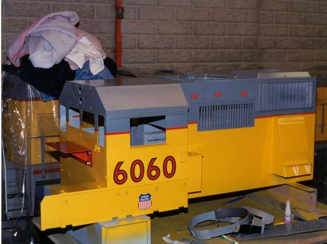
Front section complete. Large lettering is vinyl transfers.
The lettering and decals were made special for me by Connie Miracle. Miracle
Railroad Products (770)987-5982 |
|
|
|
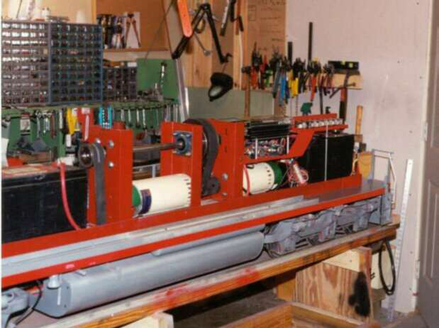
Good photo showing motors, batteries and control layout.
This should provide some of you with meat to work on. |
|
|
|
Electrical control panel before wiring. note use of
computer generated labels. |
|
|
|
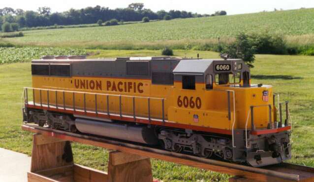
Completed SD-60 Locomotive |
|
Click HERE
for more detail pics of the completed SD-60
|