|
A Precision Steel
Car Flat Car with the "Wright" Touch
click
on images for larger view
Looking at that
box of greasy parts is somewhat intimidating. Kind of makes one think
that maybe, in this case, I better read the instructions first. The good
news is that the instructions are mostly pictures. It’s a guy thing.
I won’t purchase a book unless it has more pictures than text.
I took their advice
and assembled the whole thing as best I could using their box lid for
a work bench. This was just a dry assembly to get an idea of where all
the parts go. Next I am thinking, this would be great if I could just
glue it together. No problem…however that is not the case.
After that dry assembly,
I let it set and looked at it from time to time for a month or two. I
just wasn’t quite comfortable just starting to weld without my own
plan of attack. I could see a lot of grinding in my future if I had overlooked
something and a flat car that was not flat. In a few areas, I deviated
from Precision Steel Car's assembly instructions to make this car more
compatible with the way I build my cars and to add some additional details.
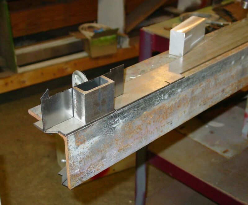
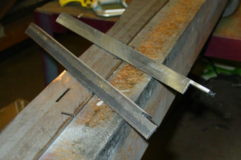
The first task was
to hold the main center parts together and keep them straight.
I solved this problem by welding a piece of 2” channel on top of
the coupler plate. It strengthens the plate and adds sides to use as a
clamp. I cut and milled these parts exactly 1.75 to match the plate and
located it so as not to be in the way of the coupler pin to be installed
later.
A long time ago when
constructing my first car, I determined that the couplers should be somewhat
adjustable up and down. I have used a standard way of doing this on every
car since and it work very well, as well as giving the car a prototype
appearance.
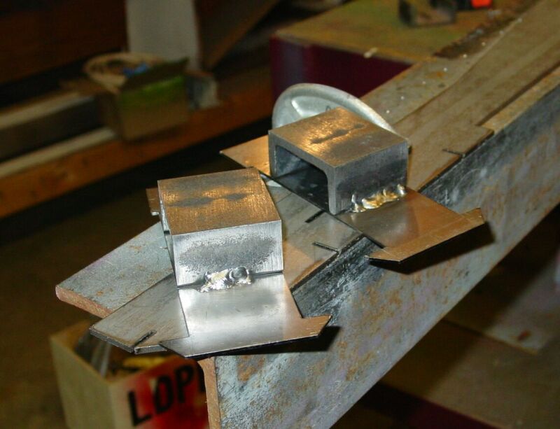
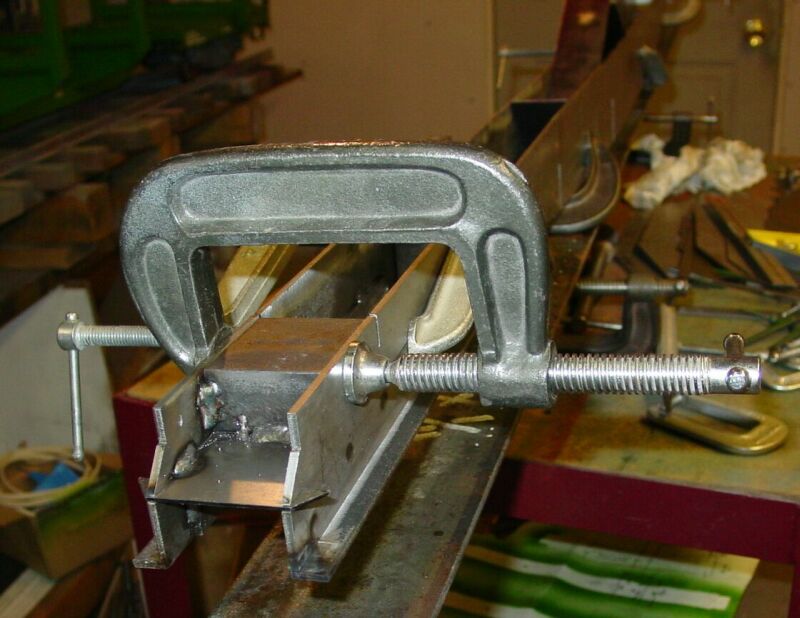
To this end I used
some 1/8” X 5/8” angle to make a bolt flange outside the center
spars.
As you can see in the photos, this give me about 1/8” more vertical
clearance in the coupler pocket. I machined about .050 off the inside
of the angle so that I did not lose all of the horizontal clearance.
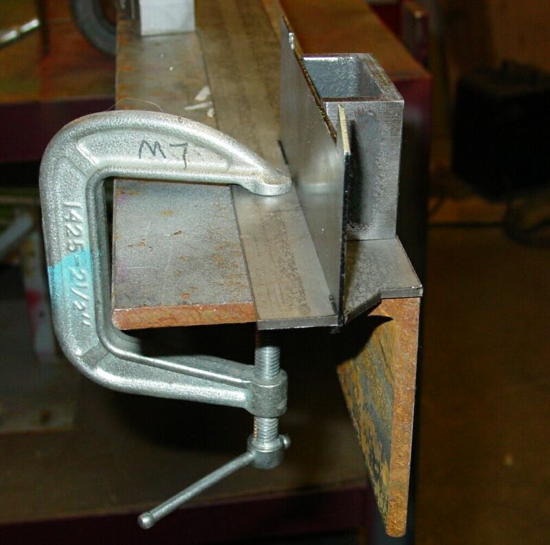
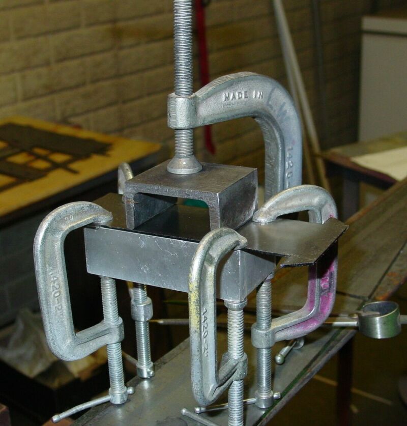
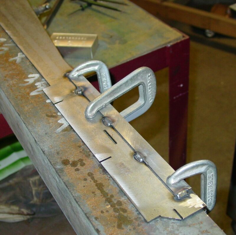
With the angle welded
onto the center frames right and left and extending ¼” past
the center pin box I set about clamping up the center frame. As exemplified
by the photos, aluminum blocks were machines also to 1.750 and used as
spacers behind the coupler pocket. This is important because welding will
draw the sides of the center frame in or out depending on where you place
the welds. We want these parts to stay parallel. Temporarily install the
frame end (as in step 4 of the instruction book) as an additional aid.
Do not weld it on yet.
When I was sure that
the parts were aligned properly the first welds were made. Note that I
am using a piece of 4” angle that is very straight to clamp the parts
to for welding.
Also, I did not follow
the instructions at this point for two reasons. The goal was to keep the
center straight and parallel. In the kit I received, the four main cross
braces were made from 1/8” material and tended to remain straight.
The bolster cross pieces and end pieces were made from 18 gauge and, with
the deep cut, could possibly be bent. PSC is in the process of changing
the end pieces to be made from 1/8" material.
Page [1] [2]
[3] [4]
>>
|