|
A Precision Steel
Car Flat Car with the "Wright" Touch
click
on images for larger view
Page <<
[1] [2] [3] [4]
>>
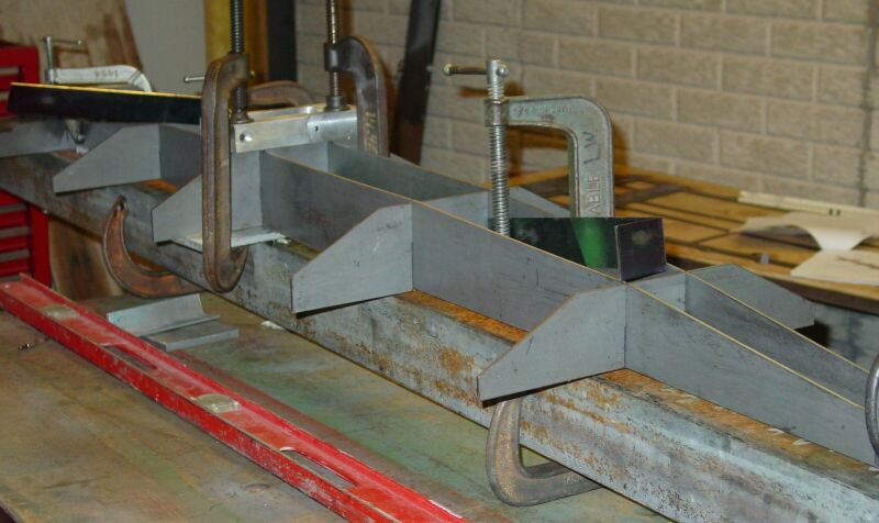
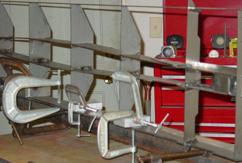
After the bolsters
were welded on both ends, I spread the center beam apart and installed
the four cross braces. I welded them one at a time making sure they were
clamped so that the tops were even with the top of the center pieces.
Also, VERY IMPORTANT, I used a straight edge on the outside of the horizontal
braces to check alignment. See red level in the photo.
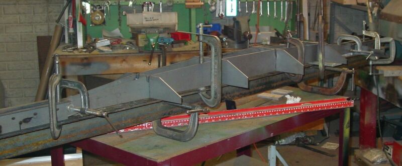
One could make a quick
fixture from some angle and clamp it to both sides before welding. I welded
one, checked, and moved to the next one and checked. This is important
because if the frame is racked at this point nothing is going to fit right.
When the car was complete I found that it had racked about .050 less than
1/16 of an inch. That was no problem.
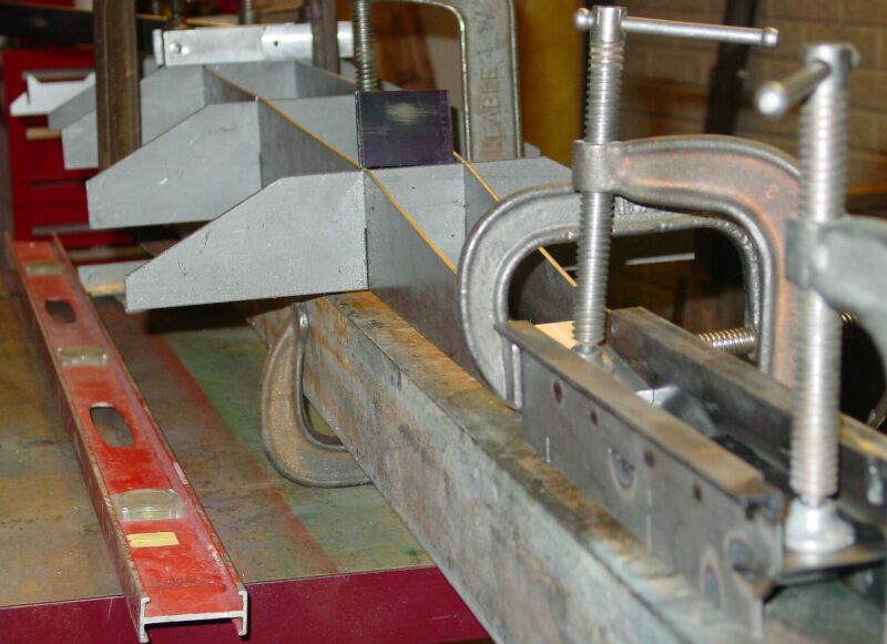
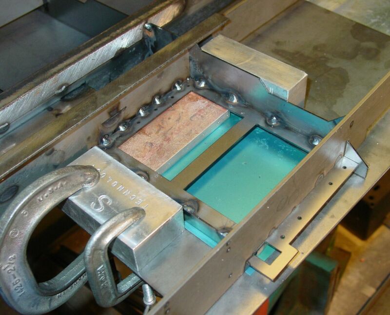
Next I positioned
the front horizontal bolster parts in their slots. I used aluminum blocks
and clamps to make sure the parts were straight and had a heat sink. I
only put on the front bolster part at this time so that the sides would
not ride back and forth on the front and back pieces making them hard
to align. Also remember, these parts are different so check and make sure
you have the correct one.
The side pieces were
clamped to the horizontal bolster using some aluminum blocks. Measurements
were taken to determine that one side rail did not stick out farther than
the other. A good carpenter square can be used for this. Once I was satisfied
with the location the sides were welded to the bolsters.
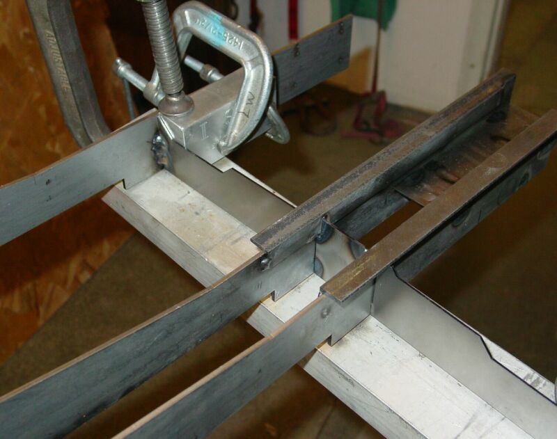
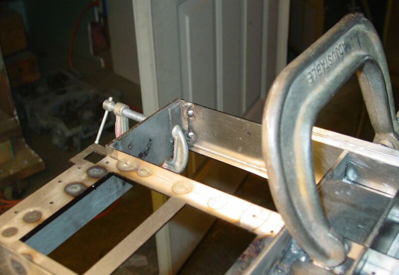
Because it is difficult
to weld vertical, the frame was clamped up right on to the 4” angle.
This kept the sides straight and made it easy to adjust the horizontal
braces for proper location before welding.
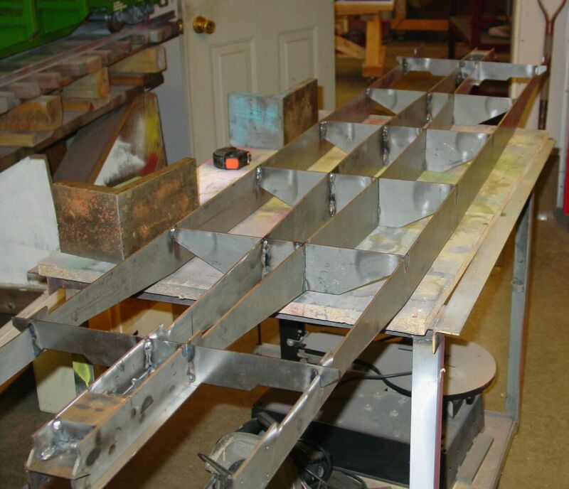
After the basic frame
was welded I installed the TOP SHEET BRACE as pictured in step 6 of the
instruction book. I backed this piece up with a piece of 1” x 1”
angle to make sure it was straight and the ends are located as per instructions.
Next came the SMALL DECK FRAMES. If they fit correctly you are home
free. I used several very small welds for this installation. Note
in the photos. |
|
|
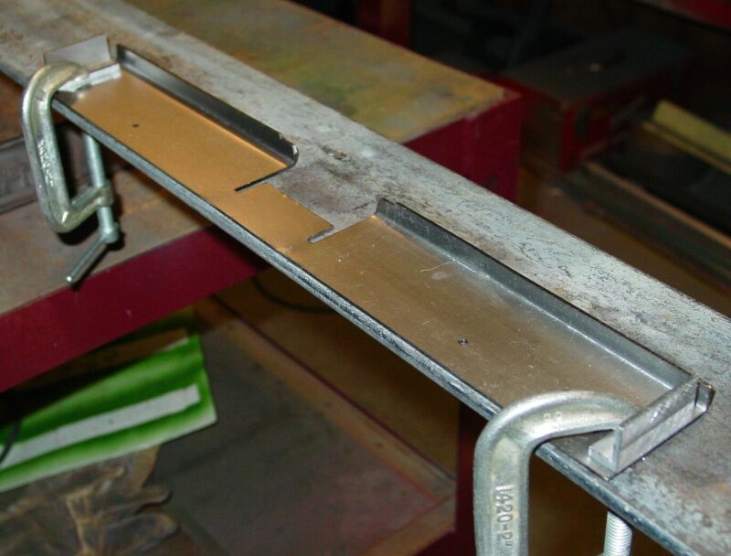
Now it is back to step 4 in the instruction book, the application
of the FRAME END. I used my brake and turned the bottom 5/16”
under forming a right angle and stiffend the part. Note:
PSC is in the process of switching this part to 1/8" material
which will greatly improve its rigidity. |
|
|
I then cut and welded on some small pieces of ½” X ½”
angle to the outside ends. This makes it much easier to weld the ends
to the sides.
Page <<
[1] [2] [3] [4]
>>
|